(Click
on under
lined
link to go to
subject)
 -
Contents -
Contents
Chapter
1. Vision System Design
Chapter
2.
Biological
Eye Designs
A. Camera
B. Pinhole
C. Concave
mirror
D.
Apposition
E. Neural
superposition
F.
Refraction
superposition
G.
Reflection
superposition
H.
Parabolic
superposition
I.
Multiple
sensor
types and
combinations of types
Chapter
3. Eye
Design Illustrations
Chapter
4. Eye
Reproduction
Chapter
5. Optical
Systems
Design
Chapter
6. The Eye Designer
Related Links
Appendix
A - Slide Show & Conference Speech by Curt Deckert
Appendix
B - Conference Speech by Curt Deckert
Appendix
C - Comments From Our Readers
Appendix
D - Panicked Evolutionists: The Stephen Meyer Controversy
|
EYE
DESIGN
BOOK
Chapter 2
Sections A, B and C
- Prev Page
Go
to Chapter Links -
 Next Page -

(Click on PICTURE
IN TEXT to bring up LARGE
PICTURE)
2. BIOLOGICAL EYE
DESIGN
Biological eye designs are classified into a number of broad
categories. Some primitive eyes, plant eyes and eyes of some creatures
do not have image-forming optical designs. These can be noted as
multiple sensor types, but there are also creatures with a mix of image
forming and non-image forming sensors. There are considerable optical
variations within each of the eye design type. For example, we find
variations in the use of simple or highly corrected compound lenses,
sensor combinations, focusing, light control, color pigments in cells,
resolution over field of view, maximum resolution, eye-supporting and
pointing structures, and in other features. This section is divided
into nine broad image-forming optical design types as follows:
A. Camera
B. Pinhole
C. Concave mirror
D. Apposition compound
E. Apposition-Neural superposition
compound
F. Refracting superposition compound
G. Reflecting superposition compound
H. Parabolic superposition compound
I. Multiple sensor types and
combinations of types
A
. Camera
Camera-type eye designs form an image on a retina (instead of film)
from eye lenses. They are found in animals of all complexities and
sizes such as humans, vertebrate animals, some aquatic creatures,
spiders, and other creatures. In general, slightly different designs
are required for small aquatic creatures such as jellyfish.
Figure 2.1 illustrates typical
optical designs for a camera-type eye, where it forms an inverted image
on the retina. (p.300, Fig. 2, Vision
Optics & Evolution by
Dan E. Nilsson, Biosciences, Vol. 39, No. 5, May 1989)
The following
variations in Camera Eye structure illustrates applications for
particular animals requiring different optical designs for their vision
systems. All are based on the same design themes.
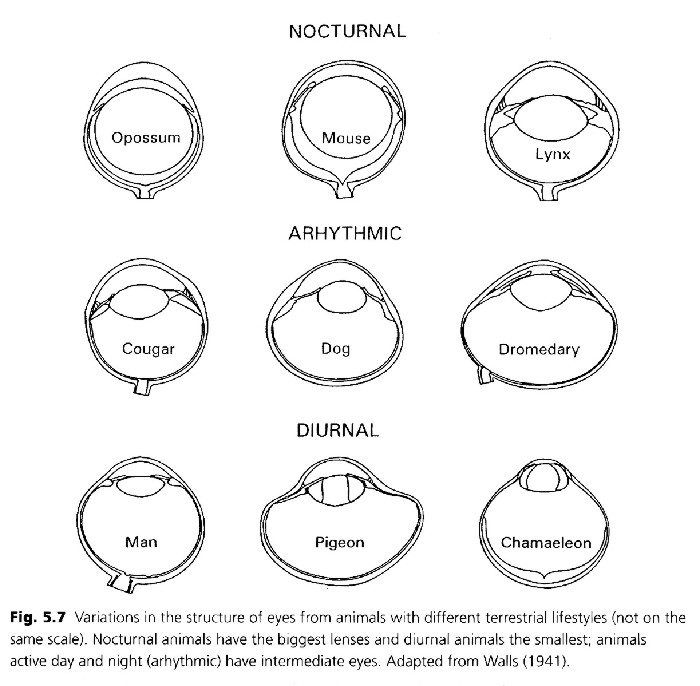
Figure 2.1a Camera
Eye Structure Durations
(Reference: Figure 5.7, p. 83, Animal
Eyes, Michael F. Land, Dan-Eric
Nilsson, Oxford Animal Biology series, Oxford University Press, 2002-
Please see their book for more details )
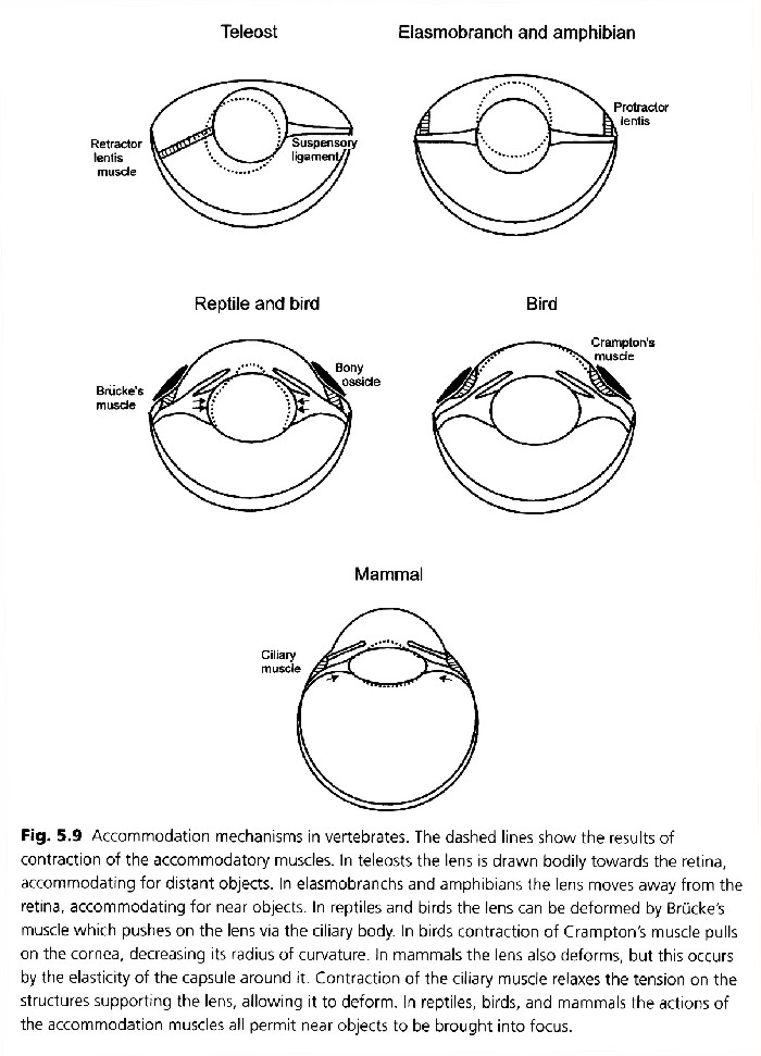
There are many
different approaches taken to focus camera type eyes. The following
figure illustrates some of the extent of different focusing mechanisms.Figure
2.1b Camera Eye Focus
(Reference: Figure 5.9, p. 85, Animal
Eyes, Michael F. Land, Dan-Eric
Nilsson, Oxford Animal Biology series, Oxford University Press, 2002-
Please see their book for more details )
Good focus is not
possible in all creatures having camera-type eyes. This is especially
true in small eyes with a fixed focal distance between lens and retina,
such as those in some fish and other aquatic animals. Precision
focusing results from interactive controls between the eye and brain.
This function is much like auto-focus lenses on man-made cameras. Some
camera-type eyes focus by changing the shape of the lens instead of
moving the lens relative to the retina. In an eye this takes place by
muscles |
Figure 2.1. Camera
Type
Optical Design variations
Fig 2.1a. Camera Eye
Structure Durations
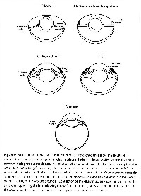
Fig 2.1b. Camera
Eye Focus
|
changing
the effective curvature of the lens from a shorter focal
length to a longer focal length.
Some
camera eye focusing takes place using hydraulic methods. Here, fluid is
moved in and out of chambers to adjust a fixed focal length lens
relative to the retina to achieve focus. In addition, amphibious
animals using this technique often need to provide radical water
pressure accommodations using hydraulic controls.
Lens materials, photoreceptors' or light sensors' resolution, shape,
size controls, color vision, and field coverage can be slightly
different for eyes of different creatures. Large creatures typically
have large visual fields with good resolution. The camera type eyes of
birds, may have very close photoreceptor cell spacing for high
resolution to see small targets at long distances. An example of an
actual camera eye is shown in Figure 2.2. (Fig 2.2a by Bruce Chambers)
(Fig 2.2b adapted from 1999 Eye Poster from Anatomical Chart Co.
Skokie, IL) |
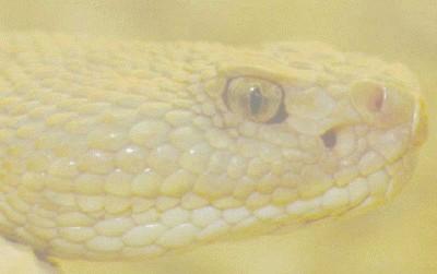 Figure 2.2a. Example
of Camera Eye
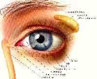 Figure 2.2b. Human
Camera Eye (Like Fig 3.44a)
|
The density of photoreceptors
at a specific point determines the resolution available at that point
in
the total field. In some variations of less-precise camera type eyes,
the
lens is so close to the retina that a clear image cannot be focused at
very close or very far object distances. Some aquatic camera eyes use
gradient
index material to help correct the lens design. Gradient index surfaces
are even difficult for man to define and to reproduce under ideal
conditions,
yet many cells, with very slight variations, grow into these unique
patterns.
Some animals use eye
scanning to achieve a larger effective field of vision with a smaller
number
of sensors. Typically, eye-pointing controls in the brain move the
eye's
center of vision to the area of interest. Normally, eye resolution is
far
less at the edges of the field of view than near the center where most
detail is seen. This is typical of camera lens systems design,
especially
in wide field applications, where it is difficult to achieve high
resolution
over a large angular field of view. The placement and integration of
each
eye sensor indicates intelligent optical design.
|
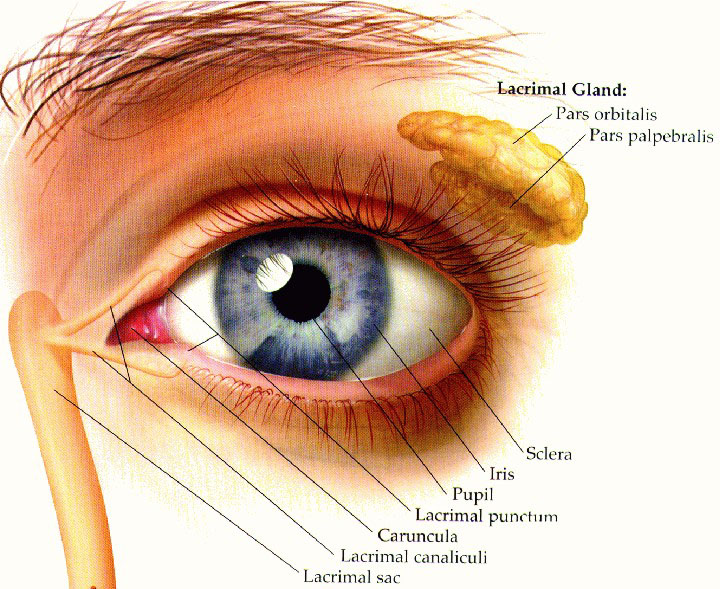
Human eye photo- receptors consist
of rods and cones. Rods operate in dim light and cones are responsible
for visual acuity and color perception. Small animals with just a few
photo-
receptor cells in small retina fields have very limited resolution.
Figure
2.3 contains a cross section of the human retina to illustrate
the design complexity of the layered sensor arrangement. (P. 31, The
Computational Eye, Frank
Werblin, Adam Jacobs, Jeff Teeters, IEEE
SPECTRUM, May 1996) |
Figure 2.3 Cross
Section of Human
Retina
|
|
There are
many different configurations of rods and cones in camera-type eyes.
Rods
and cones are shown by Figure 2.4. (P. 548, Fig. 7, Science
& Technology
Encyclopedia, McGraw
Hill) |
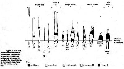
Figure 2.4. Rod and Cone
Details
|
In some creatures, rods
will have different color pigments to see efficiently in specific color
environments. Others are packaged more densely for higher resolution
and
have less emphasis on detecting many different colors. Some retinas
require
light to pass through multiple retina layers more than once instead of
just falling onto a single absorbing surface. Most biological eyes have
wide-angle vision; however, some have wide-angle scanning capability
where
the moving eye provides only narrow angle vision at each
image.
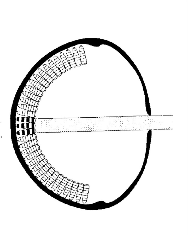
B. Pinhole
The pinhole eye
design occurs in the eyes of the nautilus, the eyes of a planarian
(flat
worm) and the eyes of other simple animal forms. This is a less complex
optical design
that does not
require a lens. Light
is not focused with a lens like the camera eye. An example of this
optical
design is the pinhole box camera that came out during the 1930's and
1940's.
This camera worked, without any lenses, by using natural optical light
diffraction to form an image. Those cameras were easily improved upon
with
simple lenses. Figure 2.5 illustrates the pinhole optical design. As
one
of the less complex optical designs it may be the most likely to occur
naturally without much intelligent optical design. This, of course,
assumes
the existence of the right mix and configuration of cells to make up
this
type of eye.
(p.300,
Fig. 2, Vision Optics
& Evolution
by Dan E. Nilsson, Biosciences, Vol. 39, No. 5, May
1989)
|
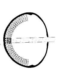
Fig 2.5 Pinhole Optical
Design (Like
Fig. 6-2)
|
The pinhole eye retina
is relatively simple and similar to the camera eye retina. It does not
have a lens (or much of a lens) so it does not provide fine optical
corrections
like the
|
camera eye, the resultant image is less clear. Variable pupils
are used to adapt
to a variety of lighting situations. It takes more light to detect a
given
scene because a bright image on the retina from a pinhole eye requires
a large pupil (small f/no.) while a sharp image focus on the retina
requires
a small pupil (large f/no.). Therefore it is difficult to obtain sharp
faint images using a pinhole optical design. |
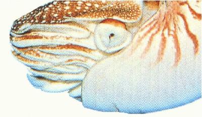
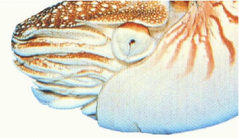
Fig
2.6. Pinhole
Eye of Nautilus
|
Insects with compound eyes,
such as flies, do not have a retina that can pre-process data, like
creatures
with pinhole or camera optics. For most insects, the total eye volume
required
for a scaled-down pinhole design would be much larger for a given
angular
field than more complex multifaceted eyes taking into account the
expected
light gathering power and resolution of each facet.
Insects achieve a greater
field of vision in small packages than they would using the pinhole
approach.
An example of a pinhole eye is shown in Figure 2.6. (P. 281, Readers
Digest,
Exploring
the Secrets of Nature, 1994)
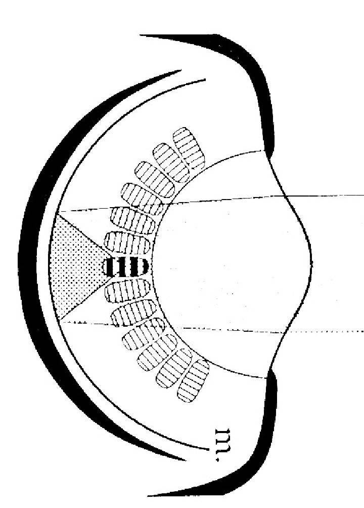
C.
Concave mirror
The concave mirror design
is found in a few small eyes. For example, when a clam opens its
protective
shell it exposes multiple eyes with a small concave mirror design. Each
small concave mirror eye forms an inverted image on small retinas like
the design shown in Figure 2.7. (p. 299, Fig. 1, Vision
Optics &
Evolution by Dan E. Nilsson,
Biosciences, Vol. 39, No. 5, May 1989)
The
large arrow represents the object the eye
is looking at and the small arrow represents the image of the large
arrow
on the retina.
Concave mirror eyes
are more complex than pinhole eyes, since they use internal concave
mirrors
to form images.
Reflective mirrors are
used as a substitute for lenses to form images on retinas. Potentially,
they can have more total image resolution in a small space |
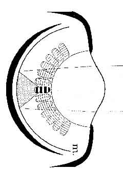
Figure 2.7 Concave
Mirror Optical Design.
|
than
pinhole eyes, because they provide better-corrected optics in a
small space. Typically, images are focused on transparent
retinas, made
up of arrays of transparent eye sensors.
|
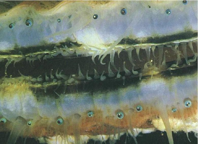
This type of eye is
like a reflective telescope design using one concave mirror instead of
a camera lens. These are not as well-known eye designs as camera type
eyes.
It is difficult to achieve a wide field of view with high resolution
using
this type of design. Adapting this design of an eye from another type
would
be difficult. An example of the concave mirror type of eye is shown in
Figure 2.8. (P. 322, Readers Digest, Exploring
the Secrets of Nature,
1994) |
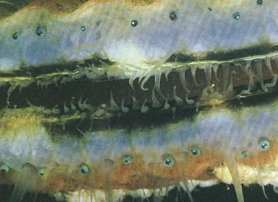
Figure 2.8 Example of
Concave
Mirror Design in Scallop Eyes
|
|
|