Chapter 1. Vision System Design
Chapter
2. Biological Eye Designs
A.
Camera
B.
Pinhole
C.
Concave
mirror
D.
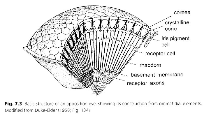
Apposition
E.
Neural
superposition
F.
Refraction superposition
G.
Reflection superposition
H.
Parabolic superposition
I.
Multiple
sensor types
and combinations of types
Chapter 3. Eye Design Illustrations
Chapter
4. Eye
Reproduction
Chapter
5. Optical
Systems
Design
Chapter
6. The Eye Designer
Related Links
Appendix
A - Slide Show & Conference Speech by Curt Deckert
Appendix
B - Conference Speech by Curt Deckert
Appendix
C - Comments From Our Readers
Appendix
D - Panicked Evolutionists: The Stephen Meyer Controversy
Chapter 2
Sections D, E and F
(Click on PICTURE IN TEXT to bring up LARGE PICTURE)
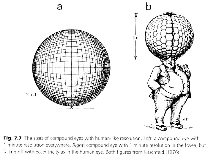
If we take the technology of a compound eye, appearing on many insects, and applied it to the requirement for human eyesight we would get an eye that is extremely large. Then if we allow the resolution to fall off with angle the eye is still so large that it would dominate the human head.This is shown on the above Figure 2.9c Equivalent Compound Eye Applied To Human Resolution
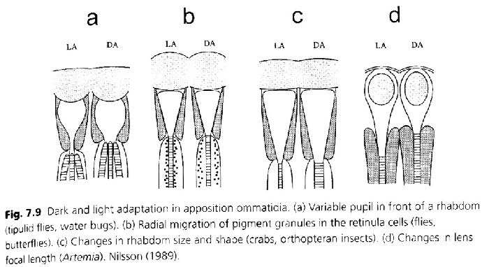
Compound eyes have unique ways of adapting to changing light. Many of these are quite diverse and indicate very sophisticated design at the micron levels. The above Figure 2.9e Light Adaptation Of Compound Eye illustrates several ways that compound eyes adapt to light.
Some crabs use this design along with some other optical designs such as distributed eyes. Compound apposition eyes of insects and sea animals contain sensors within each facet. Each sensor contains a crystalline lens and a small gradient index light pipe. The following are examples of several creatures having compound eyes. The facets making up each creature's eyes are shown for comparison with respect to the role of each in creating a complete image.
| Creature | Number of
Eye Facets |
Role Requirements for Vision |
| wood lice
small flies lobster dragonfly |
25
5,000 14,000 30,000 |
simple 2-dimension movement
complex 3-dimension movement complex 2-dimension movement complex 3-dimension movement |
E. Apposition-Neural Superposition compound
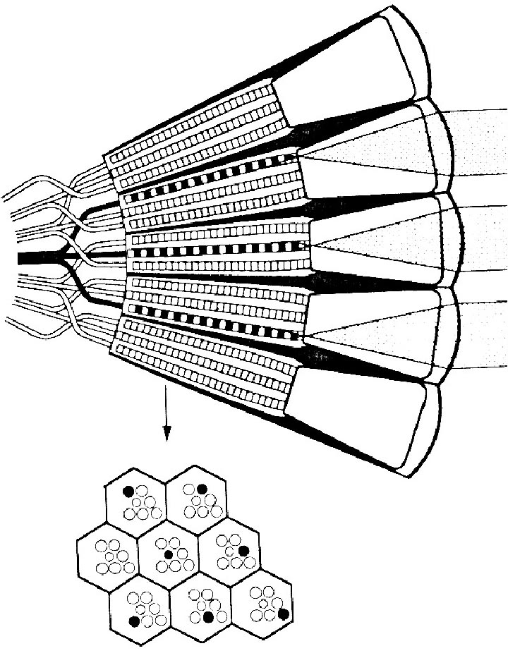
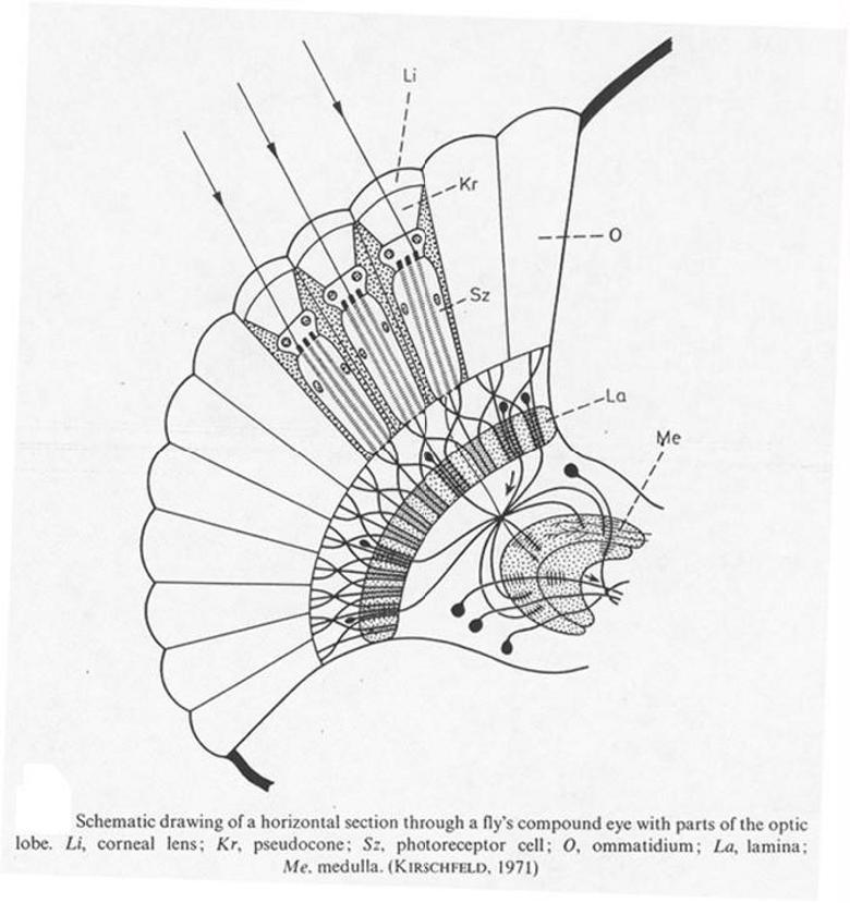
The neural or brain superposition eye has a number of small lenses arranged in a compact pattern. Each lens collects light from only a small part of the total field of view. Using the neural superposition approach, the brain puts all the small images together from the individual sensor outputs of a large number of small eye facets. Each facet contains very small light guides and sensors. Each of these facets or sets of sensors has its own optics and unique angular optical axis to pick up part of a scene, but multiple facet light inputs are combined for each segment of the image. Each segment or pixel of a scene is visualized by a series of different sensors contained in multiple facets. Output signals from combined facets can provide more sensitivity for better vision at low light levels. Typically, small flies will have this type of optical design. Where size is critical and wide-angle fields of view are required, this design is more suitable than camera eyes for small low-resolution applications. Figure 2.11 illustrates the slightly different optical design of the neural superposition eye. Image processing would need to be unique for this type of eye. Image processing is complex for any eye, but here it is even more amazing when you consider the small brain size of flies having this type of optical design. (p. 303, Fig. 3b, Vision Optics & Evolution by Dan E. Nilsson, Biosciences, Vol. 39, No. 5, May 1989)
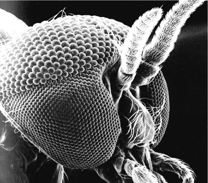
This optical design requires considerable parallel processing of visual data to provide image recognition with quick response. These eyes can operate at lower light levels when they can use the combined output from multiple facets for each point of an image to achieve greater sensitivity. (An example of an application of the neural superposition eye is shown in Figure 2.12 taken from Fig. 44, P.495, Chapter 8 PhotoChemistry of Vision, Ed. by Herbert J. A. Dastnall, Springer-Verlag, N.Y. 1972. Figure 3.12b courtesy of www.pbrc.hawaii.edu/bemf (c)MicroAngela )
Superposition Eye. (Like Fig. 6-5) |
Neural Superposition Simplified Small Fly Eye |
Insect Eye |
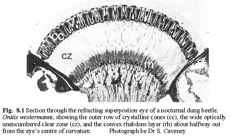
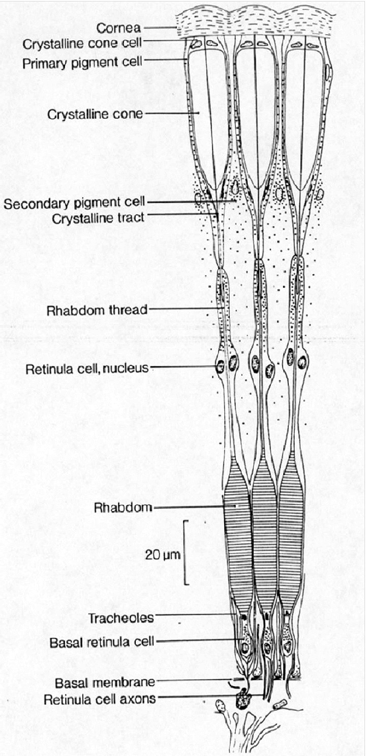
F. Refraction superposition compound
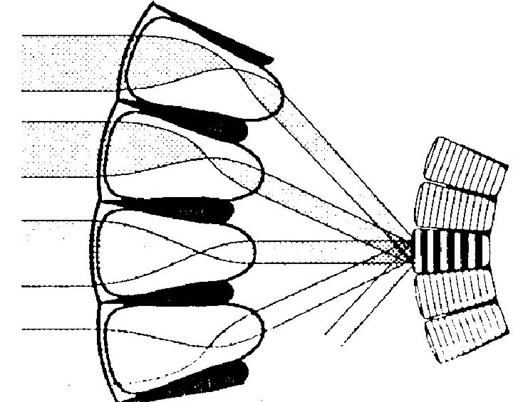
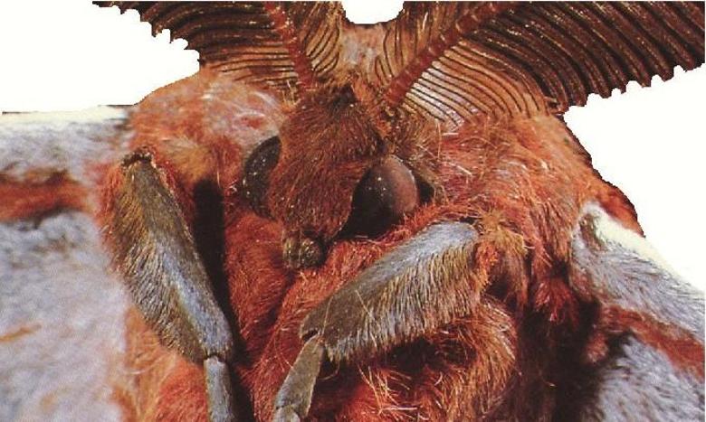
Like the previous design, this optical design would also be difficult to adapt from other eye designs. These eyes occur in moths, some flies, many beetles, and some shrimp. This optical design may be a more difficult eye to integrate, but it does give considerable design flexibility for small insect vision. It is a design where an array of clear refractive (or transmitting) crystalline cones work together as telescopic optics to produce a reversed image on a very small retina.
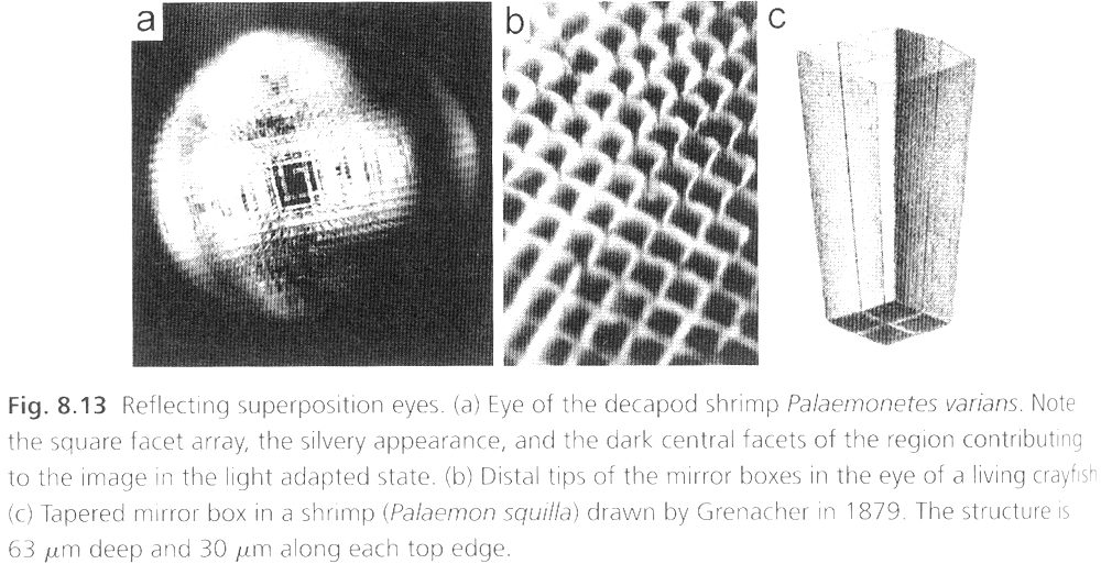
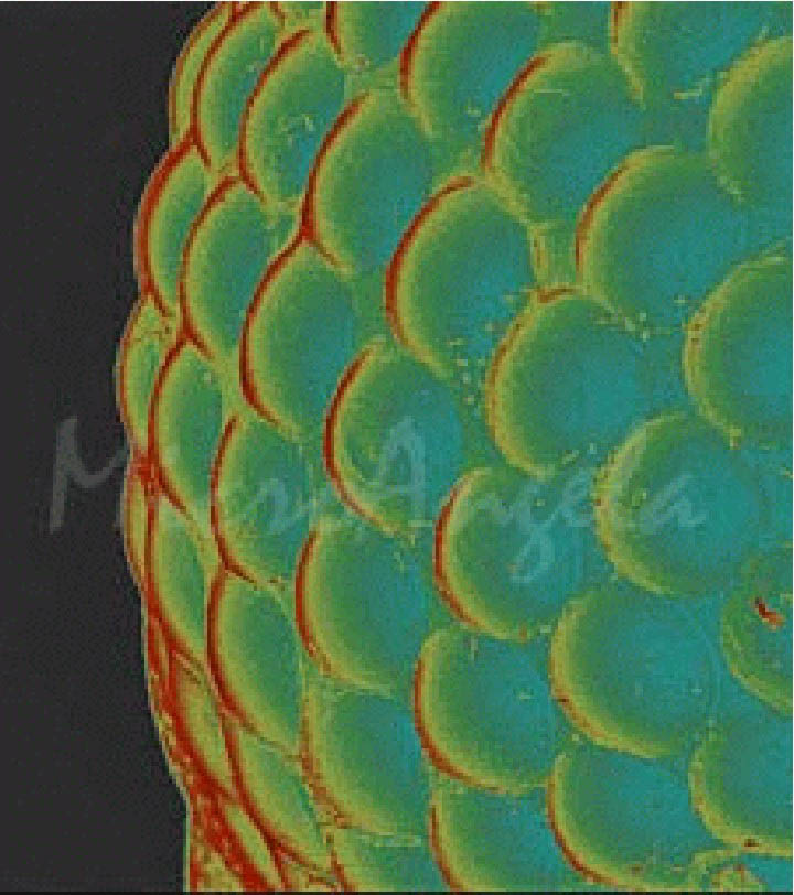
The intricate detail of reflective superposition eyes is shown on the above Figure 2.13a Reflective Superposition Example. Current MEMS technology can allow some fabrication of similar structures and optics, but the processing features indicate software intelligence that is very significant for the size of the brain interpreting the input from the eyes.
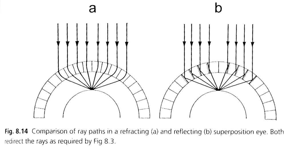
Two different approaches to Superposition Eyes are shown in the above Figure 2.13b Reflective And Refractive Superposition.
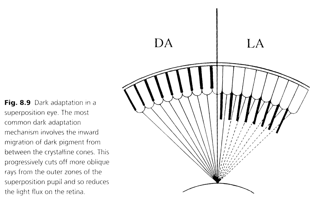
The above Figure 2.15c illustrates how the superposition eye adapts to various levels of light.
(Reference: Animal Eyes, Michael F. Land, Dan-Eric Nilsson, Oxford Animal Biology series, Oxford University Press, 2002- Please see their book for more details )
Questions for Discussion